








Fast-acting thin film fuses play an essential role in protecting modern electronic circuits against overcurrent conditions and preventing catastrophic failure events. Compact and precise, they are used in applications that demand quick response to fault events and minimal power dissipation under normal operating conditions. This article reviews the key principles behind thin film fuse operation and outlines the factors you should consider when selecting a device for your design — including current and voltage ratings, breaking capacity, temperature derating, and pulse withstand capability. Understanding these parameters helps ensure robust circuit protection in applications ranging from battery management systems to LED lighting, infotainment modules, data storage devices, and industrial control electronics.
Thin film chip fuses offer rapid and reliable interruption of excessive current, typically opening within seconds under overload conditions. Available in a range of standard surface-mount sizes (0402 to 1206) and current ratings from a few hundred milliamperes to several amperes, they provide high breaking capacities suitable for low voltage DC circuits. Their construction enables consistent performance, predictable fusing behavior, and stable characteristics over time.
These devices are commonly used for secondary, non-resettable protection where space is limited and fast action is required. Typical applications include portable and industrial equipment, Li-ion battery packs, LED drivers, and display or infotainment systems — anywhere a small, precise, and dependable overcurrent protection element is needed.
To understand how these fuses work, we'll start with the basic principle: the heat energy (Q) generated in a conductor is given by the equation Q = I²Rt, where I is the current, R is the resistance, and t is the time. This is known as the Joule effect. A fuse makes use of this principle as a safety component that interrupts current when it exceeds a predefined level. Inside the fuse, a thin film alloy melts when the heat becomes too high. Because the heat is proportional to the square of the current, higher currents generate much more heat. Once this heat exceeds the melting point of the fuse element, the fuse opens the circuit and protects your design.
Q= 2
Q= heat generated (J)
I= peak current (A)
R = electrical resistance (Ω)
t = time (s)
When you select an SMD chip fuse, you need to take several factors into account. These include the normal operating current in your circuit, the maximum operating voltage (AC or DC), the fuse's breaking capacity, the ambient operating temperature, the overload current and fusing time required for the fuse to open, and the interrupting ratings (I²t) and pulse withstand capability for inrush currents.
Fuses are temperature-sensitive devices, and their ratings have been established at a 25 °C ambient temperature. To ensure safe operation at a 25 °C ambient temperature, you should use a fuse at no more than 70 % of its rated current. For example, the S2F060332V1A00T is rated at 1 A at 25 °C, but you should not exceed 0.7 A at that temperature (Figure 1). This safety coefficient is necessary to compensates for common variations in operating conditions.
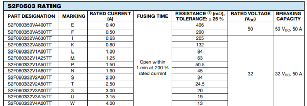
The rated voltage of a fuse indicates the maximum voltage at which it can safely interrupt a short circuit current. To protect your circuit, the fuse's rated voltage must be equal to or greater than the available circuit voltage. For instance, a fuse with a rated voltage of 32 VDC can be used in any circuit where the maximum operating voltage does not exceed 32 VDC.
Breaking capacity defines the maximum current that the fuse can safely interrupt at its rated voltage. In a fault or short circuit condition, your fuse may experience an overload current many times higher than its normal operating current. A correctly specified fuse ensures safe operation by remaining intact and clearing the circuit under these conditions.
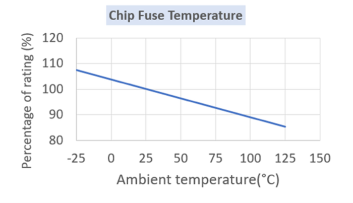
Since SMD fuses are sensitive to temperature, their ratings are based on 25 °C conditions. As the current flows, the active area of the fuse heats up due to the Joule effect, so you need to apply compensation at higher ambient temperatures. This is where the derating curve becomes essential. For example, if your circuit draws a normal operating current of 1.4 A at 25 °C with an S2F0603 fuse, you should select a 2.0 A device (1.4 A ÷ 0.70). At 60 °C, where the derating factor is 95 %, the same 1.4 A operating current would require a 2.1 A fuse (1.4 A ÷ (0.70 x 0.95)), making the S2F060332V2A50TT the recommended choice (Figure 2).
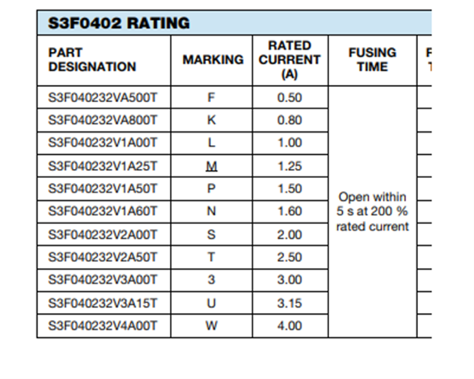
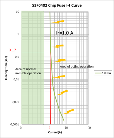
The time it takes a fuse to blow depends on both current and temperature: the higher the current, the shorter the time. Fusing curves are established under standard test conditions at 25 °C. For example, the S3F040232V1A00T has a rated current of 1 A and a fusing characteristic of 200 % IR in a maximum of 5 s, but under test conditions it fuses in just 0.17 s at 200 % IR (Figures 3a and 3b).
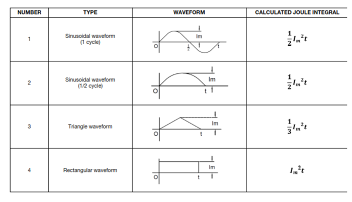
Another key parameter you need to consider is the I²t value, which represents the energy required to melt the fuse element. This value is often used to size fuses for impulse or inrush current conditions. When evaluating pulses, you must also consider the number of occurrences and the operating temperature, since repeated electrical pulses cause thermal cycling and mechanical fatigue that can shorten fuse life. For this reason, it's important to know the pulse cycle withstand capability, which specifies how many pulses of a given I²t the fuse can handle without opening, assuming there is sufficient cool-down time between pulses.
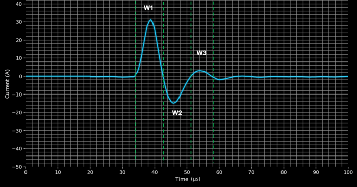
As an example, let's look at a customer requirement with a normal operating current of 1.4 A, an operating voltage of 24 V, and an ambient temperature of 60 °C. In this case, the S2F060332V2A50TT fuse is suitable. The pulse withstand requirement is 30.6 A for 100 000 cycles (Figures 4 and 5).
Breaking this down further:
W1 = 30.2A for 8 μs
W2 = 15 A for 8 μs
W3 = 3 A for 7 μs
The total I²t is calculated as 0.00457966 A²s. The S2F060332V2A50TT fuse has an I²t rating of 0.055 A²s, which is greater than the requirement. Even after applying a factor for 100 000 pulse cycles (0.01925 A²s), the fuse still meets the condition, as this remains higher than the calculated 0.00457966 A²s.
Therefore, for this set of requirements — normal operating current of 1.4 A, operating voltage of 24 V, ambient temperature of 60 °C, and inrush current pulses up to 30.6 A for 100 000 cycles —you can confidently select the S2F060332V2A50TT fuse.
Thin film fuses continue to evolve as essential components in safeguarding compact, high performance electronics. As designs move toward higher power density, faster switching speeds, and greater functional integration, these fuses provide a precise and predictable means of protecting sensitive circuits from overload and fault conditions. A clear understanding of their thermal behavior, I²t characteristics, and derating principles enables engineers to design protection schemes that are both space-efficient and reliable. Looking ahead, as electrification and miniaturization accelerate across industries — from automotive systems to connected devices — thin film fuse technology will remain a quiet but indispensable element of robust electronic design.
By Alexandre Moulin, Vishay Intertechnology, Inc.
